The LogicGatesApplet lets you build and run logic circuits to simulate those found in Chapter 1. You build the circuits using basic parts and then run them to see what patterns of input create what patterns of output.
Basic instructions
To use this applet you:
Elements of the applet
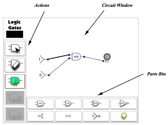
The applet has three parts, a Circuit window that displays the current circuit, a Parts Bin that allows you to add circuit elements to the Circuit Window, and an Action Panel that lets you control the circuit.

Circuit Window
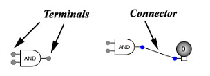
The Circuit window is on the upper right and displays the active circuit. Circuits consist of input switches, gates, terminals and output lights all tied together by connectors.
Actions
The Actions on the left are Edit, Delete and Run.
| Button | Action | Description |
|
|
Edit | The Edit action allows you to build and modify circuits by adding, moving and connecting circuit elements. This action will also reset all circuit elements to an off state. |
|
|
Delete | Clicking on a circuit element or connector deletes it. |
|
|
Run | Runs the circuit simulation to compute the values of circuit elements from the input values. |
Parts Bin
The Parts Bin on the bottom has eight buttons that add circuit elements to the Circuit Window. There are three types of circuit elements. Gates (AND, OR, XOR and NOT) that compute Boolean operations; pass throughs (Splitter and Pad) that do not compute but simply pass the signal on; and I/O element (Input switch and Output light) that originate and display signals.
| Button | Circuit Element | Description |
|
|
AND gate 2 in, 1 out |
Outputs a 1 when both inputs are 1. |
|
|
OR gate 2 in, 1 out |
Outputs a 1 when either input is 1. |
|
|
XOR gate 2 in, 1 out |
Outputs a 1 when one input is 1 and the other 0. |
|
|
NOT gate 1 in, 1 out |
Outputs a 1 when the input is 0. |
|
|
Splitter 1 in, 2 out |
Takes the input value to two outputs without change. Useful to take a single input to two gates or lights. |
|
|
Pad 1 in, 1 out |
Takes the input value to one output without change. Useful to route connectors around gates. |
|
|
Input switch 1 out |
Produces a single input value of 0 or 1. Changes when clicked in Run mode. |
|
|
Output light 1 in |
Displays a 0 or 1 as the output of a circuit during run mode. Displays as off in |
|
Each circuit element has terminals, either 1, 2 or 3, which allow connection to other elements. |

|
Tutorial Example
This example shows the building of a circuit with one AND gate.
| Illustration | Procedure | Notes |

|
Step 1. Add the required circuit gates and move them into place. Steps 1 to 3 use the Edit action. | Gates may be added, moved and connected in any order. |

|
Step 2a. Connect circuit inputs and output terminals by dragging the mouse pointer from one to another. | The terminals will turn red when active. You can drag from input to output, or output to input, and the same connector is made. |

|
Step 2b. When a partial connector reaches a second terminal it changes color. | The terminals will turn blue when a connection is complete. |

|
Step 3. A circuit is complete when all terminals have a connection. | |

|
Step 4. Select the Run action and the input values will propagate through the circuit. | Connectors are thin for a 0 signal, thick and darker for a 1 signal. |

|
Step 5. Clicking on an Input switch while using the Run action causes the circuit to change. |