ACM International Collegiate Programming Contest
Southwestern European Regional Contest
ETH Zurich, Switzerland, December 9, 1995
Problem Set
Contents
Rules and Advice
Problem A: Intersection
Problem B: Synchronous Design
Problem C: Graph Coloring
Problem D: Triangle
Problem E: Anagram
Problem F: Spreadsheet
Problem G: Cube
Problem H: Peter's Calculator
Problem J: Partial Differential Equations
Sponsored by Microsoft
Supported by Union Bank of Switzerland
Some Rules and Advice
All questions require you to read the test data from a single input file
and to write the results to a single output file. The names of both files
are given in the header of the problem. Your are not allowed to read or
write any other files than the specified ones. Standard input and output
are also considered files.
Output must correspond exactly to the provided sample output, including
spelling and spacing.
All lines (including the last one) should be terminated with a new-line
character, and no whitespace should appear at the end of a line unless explicitly
specified. Tabs should never be used.
All programs will be re-compiled prior to testing with the judges' data.
Non-standard libraries may not be used in your solutions. C programs may
not include any files except: ctype.h, math.h, stdio.h,
stdlib.h, string.h, and strings.h. Pascal programs
may use the extended Reset, Rewrite and the Close
statement, which are not part of the ISO Pascal standard.
After analyzing a program, the judges will send one of the following messages:
- Program accepted. Your program passed all tests and is accepted
as correct.
- Compile-time error. The judges were not able to successfully
compile your program. The compiler returned an error (not just a warning).
- Run-time error. Your program "crashed", i. e. it exited
prematurely due to a run-time error.
- Wrong answer. The program run through one or more test cases
without a run-time error but the output did not match the expected output.
- Presentation error. The output seems to be correct but it is
not presented in the required format. Since it is not always easy to distinguish
this message from the wrong answer message, it is only sent in obvious
cases.
- Time-limit exceeded. Your program did not finish within the
given amount of time.
- Contest rule violation. Your program violates a contest rule
like calling non-standard libraries.
Programming style is not considered in this contest. You are free to
code in whatever style you prefer.
The CPU time limit for all problems is 3 minutes except when specified otherwise.
All questions regarding the contest material should be submitted to the
judges by filling in a clarification request form. You can ask the
runners in the room for any non-contest related matters or for getting
your printer output. The helpers will not answer any questions regarding
the contest material.
Judges' decisions are to be considered final. No cheating will be tolerated.
Success!
Problem A: Intersection
Source file: intersection.c / intersection.p
Input file: intersection.in
Output file: intersection.out
You are to write a program that has to decide whether a given line segment
intersects a given rectangle.
An example:
line: start point: (4,9)
end point: (11,2)
rectangle: left-top: (1,5)
right-bottom: (7,1)
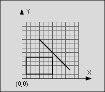
Figure 1: Line segment does not intersect rectangle
The line is said to intersect the rectangle if the line and the rectangle
have at least one point in common. The rectangle consists of four straight
lines and the area in between. Although all input values are integer numbers,
valid intersection points do not have to lay on the integer grid.
Input
The input consists of n test cases. The first line of the input
file contains the number n. Each following line contains one test
case of the format: xstart ystart xend yend xleft ytop xright ybottom
where (xstart, ystart) is the start and (xend, yend)
the end point of the line and (xleft, ytop) the top left and
(xright, ybottom) the bottom right corner of the rectangle.
The eight numbers are separated by a blank. The terms top left and
bottom right do not imply any ordering of coordinates.
Output
For each test case in the input file, the output file should contain
a line consisting either of the letter "T" if the line segment
intersects the rectangle or the letter "F" if the line segment
does not intersect the rectangle.
Example
Input
1
4 9 11 2 1 5 7 1
Output
F
Problem B: Synchronous Design
Source file: synchronous.c / synchronous.p
Input file: synchronous.in
Output file: synchronous.out
The designers of digital integrated circuits (IC) are very concerned about
the correctness of their designs because, unlike software, ICs cannot be
easily tested. Real tests are not possible until the design has been finalized
and the IC has been produced.
To simulate the behavior of a digital IC and to more or less guarantee that
the final chip will work, all of today's digital ICs are based on a synchronous
design.
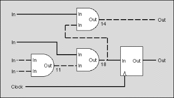
Figure 1: The critical path (dashed line) takes 43ns to settle
In a synchronous design, an external clock signal triggers the IC to go
from a well defined and stable state to the next one. On the active edge
of the clock, all input and output signals and all internal nodes are stable
in either the high or low state. Between two consecutive edges of the clock,
the signals and nodes are allowed to change and may take any intermediate
state. The behavior of a synchronous network is predictable and will not
fail due to hazards or glitches introduced by irregularities of the real
circuit.
To analyze whether an IC has a synchronous design, we distinguish between
synchronous and asynchronous nodes. Flip flops are synchronous
nodes. On the active edge of the clock, the output of the flip flop changes
to the state of the input and holds that state throughout the next clock
cycle. Synchronous nodes are connected to the clock signal.
Simple gates like ANDs or ORs are asynchronous nodes. Their output changes
- with a short delay - whenever one of their inputs changes. During that
transition phase, the output can even go into some undefined or intermediate
state.
For simplicity, we assume that all inputs of the circuits are directly connected
to the output of a synchronous node outside the circuit and that all outputs
of the circuit are directly connected to the input of a synchronous node
outside the circuit.
For an IC to have a synchronous design, mainly two requirements must be
met:
- The signal delay introduced between two synchronous nodes must
be smaller or equal than the clock period so there is enough time for nodes
to become stable. In figure 1, the round-ended boxes are asynchronous nodes
whereas the square boxes are synchronous nodes. The delay introduced on
the dashed path is 43ns and exceeds the given clock period of 30ns.
- There may be no cycles composed exclusively of asynchronous
nodes. In the real circuit such cycles could oscillate. In figure 2, the
dashed path constitutes a cycle of asynchronous nodes.
Figure 3 shows a circuit with a synchronous design. It does not contain
cycles composed of asynchronous nodes and the longest path between two synchronous
nodes is shorter than the clock period of 30ns.
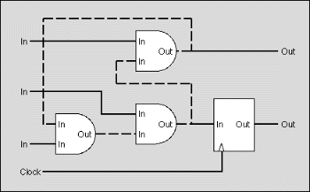
Figure 2: The design contains a cycle (dashed line)
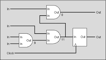
Figure 3: A synchronous design
Your are to write a program that decides for a given IC whether it has a
synchronous design or not. You are given a network of synchronous and asynchronous
nodes, a delay for each node, some inputs and outputs and the clock period.
You may safely assume that
- the delays introduced between any input and any output of the same
node are equal, i.e. equal to the delay given for that node,
- synchronous nodes have no delay at all,
- all connections between two nodes connect an output to an input.
Input
The input file contains several circuits. The first line gives the number
of circuits in the file.
For each circuit in the file, the first line contains the clock period for
the circuit, given as an integer number in nanoseconds. The next line gives
the number of nodes. The following lines each contain a node, described
by a letter and a integer number. The letter is 'i' for an input, 'o' for
an output, 'a' for an asynchronous node and 's' for a synchronous node.
The number gives the delay introduced by the node as an integer number in
nanoseconds (only meaningful for an asynchronous node). Nodes are implicitly
numbered, starting at zero.
After the nodes, the number of connections for the circuit follows. Each
following line contains a pair of integer numbers denoting a connection
between the output and the input of two nodes. The connection links an output
of the node given by the first number and an input of the node given by
the second number.
The clock signal is not given in the input file. We assume that all synchronous
nodes are properly connected to the clock signal.
Output
For each circuit in the input file, your output file should contain a
line with one of the following messages:
- "Synchronous design. Maximum delay: <ss>."
if the circuit has a synchronous design. <ss> should be replaced
by the longest delay found on any path between two synchronous nodes.
- "Circuit contains cycle." if the circuit contains
a cycle composed exclusively of asynchronous nodes.
- "Clock period exceeded." if there is a path between
two synchronous nodes that is longer than the given clock period and there
are no cycles composed of asynchronous nodes.
Example
Input
1
30
10
i 0
i 0
i 0
i 0
o 0
o 0
a 9
a 11
a 8
s 0
9
0 8
1 7
2 6
2 6
6 7
7 8
8 4
7 9
9 5
Output
Synchronous design. Maximum delay: 28
Problem C: Graph Coloring
Source file: coloring.c / coloring.p
Input file: coloring.in
Output file: coloring.out
You are to write a program that tries to find an optimal coloring for a
given graph. Colors are applied to the nodes of the graph and the only available
colors are black and white. The coloring of the graph is called optimal
if a maximum of nodes is black. The coloring is restricted by the rule that
no two connected nodes may be black.
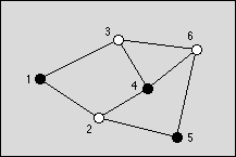
Figure 1: An optimal graph with three black nodes
Input
The graph is given as a set of nodes denoted by numbers 1...n,
n <= 100, and a set of undirected edges denoted by pairs
of node numbers (n1, n2), n1 != n2. The
input file contains m graphs. The number m is given on the
first line. The first line of each graph contains n and k,
the number of nodes and the number of edges, respectively. The following
k lines contain the edges given by a pair of node numbers, which
are separated by a space.
Output
The output should consists of 2m lines, two lines for each graph
found in the input file. The first line of should contain the maximum number
of nodes that can be colored black in the graph. The second line should
contain one possible optimal coloring. It is given by the list of black
nodes, separated by a blank.
Example
Input
1
6 8
1 2
1 3
2 4
2 5
3 4
3 6
4 6
5 6
Output
3
1 4 5
Problem D: Triangle
Source file: triangle.c / triangle.p
Input file: triangle.in
Output file: triangle.out
A triangle is a basic shape of planar geometry. It consists of three straight
lines and three angles in between. Figure 1 shows how the sides and angles
are usually labeled.
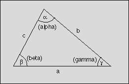
Figure 1: Triangle
A look into a book about geometry shows that many formulas for triangles
exist:


The values of a, b, c, alpha, beta,
and gamma form a set of six parameters that fully define a triangle.
If a large enough subset of these parameters is given, the missing ones
can be calculated by using the formulas above.
You are to write a program that calculates the missing parameters for a
given subset of the six parameters of a triangle. For some sets of parameters,
it is not possible to calculate the triangle because either too few is known
about the triangle or the parameters would lead to an invalid triangle.
The sides of a valid triangle are greater than 0 and the angles are greater
than 0 and less than pi. Your program should detect this case and output:
"Invalid input." The same phrase should be output if
more than the minimal set needed to compute the triangle is given but the
parameters conflict with each other, e.g. all three angles are given but
their sum is greater than pi.
Other sets of parameters can lead to more than one but still a finite number
of valid solutions for the triangle. In such a case, your program should
output: "More than one solution."
In all other cases, your program should compute the missing parameters and
output all six parameters.
Input
The first line of the input file contains a number indicating the number
of parameter sets to follow. Each following line consists of six numbers,
separated by a single blank character. The numbers are the values for the
parameters a, alpha, b, beta, c, and
gamma respectively. The parameters are labeled as shown in figure
1. A value of -1 indicates that the corresponding parameter is undefined
and has to be calculated. All floating-point numbers include at least eight
significant digits.
Output
Your program should output a line for each set of parameters found in
the input file. If a unique solution for a valid triangle can be found for
the given parameters, your program should output the six parameters a,
alpha, b, beta, c, gamma, separated by
a blank character. Otherwise the line should contain the phrase "More
than one solution." or "Invalid input." as
explained above.
The numbers in the output files should include at least eight significant
digits. Your calculations should be precise enough to get the six most significant
digits correct.
Example
Input
3
62.72048064 2.26853639 -1.00000000 0.56794657 -1.00000000 -1.00000000
15.69326944 0.24714213 -1.00000000 1.80433105 66.04067877 -1.00000000
72.83685175 1.04409241 -1.00000000 -1.00000000 -1.00000000 -1.00000000
Output
62.72048064 2.26853639 44.02668698 0.56794657 24.58722491 0.30510970
Invalid input.
Invalid input.
Problem E: Anagram
Source file: anagram.c / anagram.p
Input file: anagram.in
Output file: anagram.out
You are to write a program that has to generate all possible words from
a given set of letters.
Example
Given the word "abc", your program should - by exploring all
different combination of the three letters - output the words "abc",
"acb", "bac", "bca", "cab" and "cba".
In the word taken from the input file, some letters may appear more than
once. For a given word, your program should not produce the same word more
than once, and the words should be output in alphabetically ascending order.
Input
The input file consists of several words. The first line contains a number
giving the number of words to follow. Each following line contains one word.
A word consists of uppercase or lowercase letters from A to Z. Uppercase
and lowercase letters are to be considered different.
Output
For each word in the input file, the output file should contain all different
words that can be generated with the letters of the given word. The words
generated from the same input word should be output in alphabetically ascending
order.
Example
Input
2
abc
acba
Output
abc
acb
bac
bca
cab
cba
aabc
aacb
abac
abca
acab
acba
baac
baca
bcaa
caab
caba
cbaa
Hint
The number of possible combinations raises very quickly with the number
of given letters. Make sure you do not use long words for testing your program
because the output file could become very big, waste a lot of space on the
disk and degrade the performance of the network.
Problem F: Spreadsheet
Source file: spreadsheet.c / spreadsheet.p
Input file: spreadsheet.in
Output file: spreadsheet.out
In 1979, Dan Bricklin and Bob Frankston wrote VisiCalc, the first spreadsheet
application. It became a huge success and, at that time, was the killer
application for the Apple II computers. Today, spreadsheets are found on
most desktop computers.
The idea behind spreadsheets is very simple, though powerful. A spreadsheet
consists of a table where each cell contains either a number or a formula.
A formula can compute an expression that depends on the values of other
cells. Text and graphics can be added for presentation purposes.
You are to write a very simple spreadsheet application. Your program should
accept several spreadsheets. Each cell of the spreadsheet contains either
a numeric value (integers only) or a formula, which only support sums. After
having computed the values of all formulas, your program should output the
resulting spreadsheet where all formulas have been replaced by their value.
 A1    B1     C1     D1     E1     F1     ...
 A2    B2     C2     D2     E2     F2     ...
 A3    B3     C3     D3     E3     F3     ...
 A4    B4     C4     D4     E4     F4     ...
 A5    B5     C5     D5     E5     F5     ...
 A6    B6     C6     D6     E6     F6     ...
 ...   ...    ...    ...    ...    ...    ...
Figure 1: Naming of the top left cells
Input
The first line of the input file contains the number of spreadsheets
to follow. A spreadsheet starts with a line consisting of two integer numbers,
separated by a space, giving the number of columns and rows. The following
lines of the spreadsheet each contain a row. A row consists of the cells
of that row, separated by a single space.
A cell consists either of a numeric integer value or of a formula. A formula
starts with an equal sign (=). After that, one or more cell names follow,
separated by plus signs (+). The value of such a formula is the sum of all
values found in the referenced cells. These cells may again contain a formula.
There are no spaces within a formula.
You may safely assume that there are no cyclic dependencies between cells.
So each spreadsheet can be fully computed.
The name of a cell consists of one to three letters for the column followed
by a number between 1 and 999 (including) for the row. The letters for the
column form the following series: A, B, C, ..., Z, AA, AB, AC, ..., AZ,
BA, ..., BZ, CA, ... ZZ, AAA, AAB, AAC, ... AAZ, ABA, ..., ABZ, ACA, ...,
ZZZ. These letters correspond to the number from 1 to 18278. The top left
cell has the name A1. See figure 1.
Output
The output of your program should have the same format as the input,
except that the number of spreadsheets and the number of columns and rows
are not repeated. Furthermore, all formulas should be replaced by their
value.
Example
Input
1
4 3
10 34 37 =A1+B1+C1
40 17 34 =A2+B2+C2
=A1+A2 =B1+B2 =C1+C2 =D1+D2
Output
10 34 37 81
40 17 34 91
50 51 71 172
Problem G: Cube
Source file: cube.c / cube.p
Input file: None
Output file: cube.out
There was once a 3 by 3 by 3 cube built of 27 smaller cubes. It has fallen
apart into seven pieces:
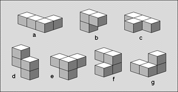
Figure 1: The seven pieces that once formed a cube
The seven pieces can be assembled in many ways to again form the cube. Figure
2 shows one of these possibilities. The first square stands for the front
plane, the next one for the middle plane and the last one for the back plane
of the cube. The letters in the cells stand for the name of piece filling
out the corresponding space in the cube. The name of the seven pieces can
be found in figure 1.
a   d   c      d   d   g      d   g   g
a   c   c      b   f   g      b   f   e
a   a   c      f   f   e      b   e   e


a   a   b      f   f   e      f   e   e
a   b   b      g   f   c      g   g   e
a   d   c      d   d   c      d   g   c
Figure 2: Two possibilities of assembling the cube
You are to write a program that outputs all possibilities of assembling
the cube but suppress solutions that are mere rotations of another solution.
The time limit for this problem is 15 minutes!
Input
No input is needed.
Output
For each solution found, your program should output a line containing
the solution as a string. The string is a linearized form of the cube. Each
letter stands for the piece filling out the corresponding space in the cube.
It is linearized as follows:
- The string consists of substrings representing the front, middle and
back plane.
- Each substring consists of substrings representing the top, middle
and bottom row.
- Each row substring consists of letters representing the left, middle
and right cell.
The solutions in figure 2 would be represented like this:
adcaccaacddgbfgffedggbfebee
aababbadcffegfcddcfeeggedgc
It is very important that your program uses the naming convention given
in figure 1 and linearizes the cube as explained above.
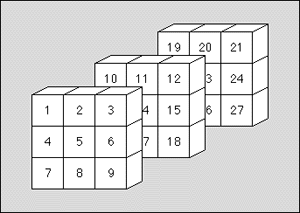
Figure 3: Positions of the cells in the string
Figure 3 again shows how the cells of the cube are linearized.
Example
The output of your program could start like this:
aababbadcggeffcddcgeegfedfc
aababbadceffgdcgdceefedfggc
aababbadcffegfcddcfeeggedgc
...
Hint
Piece a is the only part that, by rotation and translation, cannot
be transformed into itself. In order to avoid solutions that are mere rotations
of an already found solution, you may restrict transformations of piece
a to translations.
Problem H: Peter's Calculator
Source file: calculator.c / calculator.p
Input file: calculator.in
Output file: calculator.out
Unfortunately, Peter's Calculator broke down last week. Now Peter is left
with his computer, which has no calculator application, and paper and pencil,
which is too tiresome for an engineer. As one of Peter's friends, you are
asked to write him a calculator application. After talking to him, you figure
out the following:
- Peter does only integer arithmetic. The operations he needs are addition,
subtraction and multiplication.
- He would like to use an arbitrary number of variables whose names are
not longer than 50 characters.
- His main way of doing calculations are to type in a few formulas and
to assign them to variables. Some formulas are complicated expressions,
which can refer to yet undefined variables, while other formulas consist
of a single number. Then Peter asks for the value of some variables, i.e.
he evaluates the formulas.
- Peters wants to redefine some variables and then to reevaluate formulas
that depend on these variables.
The input strictly adheres to the following syntax (given in EBNF):
file = line { line } <EOF>.
line = [ assignment | print | reset ] <CR>.
assignment = var ":=" expression.
print = "PRINT" var.
reset = "RESET".
expression = term { addop term }.
term = factor { mulop factor }.
factor = "(" expression ")" | var | number.
addop = "+" | "-".
mulop = "*".
In the Extended Backus-Naur Formalism (EBNF), A = B C declares
that the grammatical construct A consists of a B followed
by a C. A = B | C means that A consists of a
B or, alternatively, of a C. A = [ B ] defines
construct A to be either a B or nothing and A = {
B } tells you that A consists of the concatenation of any
number of Bs (including none).
The production var stands for the name of a variable, which starts
with a letter followed by up to 49 letters or digits. Letters may be uppercase
or lowercase. The production number stands for a integer number.
The precise syntax for these productions are given below. The case of letters
is important for both variables and statements.
var = letter { letter | digit }.
number = [ "-" ] digit { digit }.
letter = "A" | "B" | ... | "Z" | "a" | "b" | ... | "z".
digit = "0" | "1" | ... | "8" | "9".
Between the parts of a grammatical construct but not within the names
of variables or integer numbers, any number of spaces may appear. <EOF>
stands for the end of the input file and <CR> stands for the new-line
character. All lines in the input file are shorter than 200 characters.
The value of a variable is said to be undefined:
- if it has not yet been defined or it refers to a variable, which has
not yet been defined;
- if the definition of the variable contains a cycle.
Your are to write a program that implements Peter's calculator. It should
store all variable definitions and for each "PRINT" statement
evaluate the specified variable based on the latest variable definitions.
If your program encounters a "RESET" statement, it should delete
all stored variables so that all variables become undefined.
Input
The input file contains calculations adhering to the syntax given above.
Each line contains either an assignment to a variable, a "PRINT"
statement, a "RESET" statement or nothing.
Output
For each "PRINT" statement found in the input file, your program
should output a line containing the numerical value of the specified variable
or the word "UNDEF" if the variable is undefined.
Example
Input
a := b + c
b := 3
c := 5
PRINT d
PRINT a
b := 8
PRINT a
RESET
PRINT a
Output
UNDEF
8
13
UNDEF
Problem J: Partial differential equations
Source file: equation.c / equation.p
Input file: equation.in
Output file: equation.out
In engineering sciences, partial differential equations play an important
and central role. For example, the temperature of a metal plate can be expressed
as a partial differential equation if the temperature on the boundaries
is known. This is called a boundary value problem.
Usually, it is not easy to solve these problems. Analytical solutions exist
only in very special cases. But there are some more or less "good"
numerical ways to solve boundary value problems.
We now will look at one method which works with finite difference approximations
for the derivatives of a function. For this approach, we do not look at
an analytical function u(x) but we are only interested in
the values of u at a finite set of discrete points xi:
ui = u(xi). The distance between two adjacent
points, xi and xi+1, is constant: h
= xi+1 - xi (cf. figure 1).
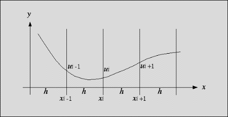
Figure 1: u(x) at some discrete points xi
The finite difference approximation of a first derivative of the function
u(x) is
 (1)
(1)
The second derivative is approximated by
 (2)
(2)
This approximation works with 2-dimensional functions u(x,
y) as well. For simplicity we only work on square problems, i.e.
(x, y) is element of [0,1] x [0,1]. Again, the area of the
function is discretized in a similar way: xi+1 - xi
= yi+1 - yi = h = 1 / n,
for some integer n >= 2. We only look at the values of u(x,
y) at the discrete points Pk = (xi,
yj): ui,j = u(Pk).
With this discretization, we have a function ui,j
as shown in figure 2:
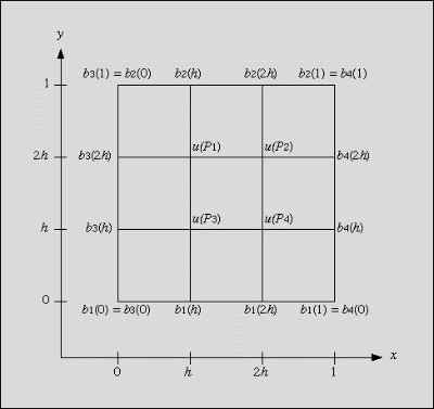
Figure 2: Function ui,j in the discretization area
On the boundary, u(xi, yj) is
given by 4 known functions:
 (3)
(3)
The points Pk cover the inner points of the discretization
area, i.e. the area without the boundary. They are numbered from left to
right and from top to bottom like English text.
What we now want to do is to solve the poisson-equation in the area [0,1]
x [0,1]:
 (4)
(4)
with the above boundary conditions. f(x, y) is a
given 2-dimensional function. With equation (2) and the above discretization,
the poisson-equation can be approximated at
 , (5)
, (5)
where fi,j is the function f(x,
y), evaluated at the discrete points (xi, yj).
Formula (5) can be written in a more readable form, depending on the position
of the discrete points:
 (6a)
(6a)
A similar equation, which we will use as an example below, is:
 (6b)
(6b)
We call the 3x3 matrix on the left hand side v and the 3x3 matrix
on the right hand side g. Now, equation (6b) can be formulated in
every point of the discrete area of figure 2:
 (7)
(7)
(7) is a linear equation system for the values of u(x,
y) at the points P1, P2, P3
and P4.
By rearranging and adding the terms on each line, the linear equation system
can be formulated as:
az = b (8)
where a is a 4x4 matrix and b is a vector with 4 elements. Vector
z represents the unknown values of u(x, y) at
the points P1, P2, P3
and P4.
You are to write a program that creates the linear equation system (7) in
the form (8) for any two matrices v and g (6). As input, the
two matrices v and g and the functions b1,
b2, b3, b4, and f
are given. Also, a parameter n is given as the number of discretization
intervals. Thus, h = 1/n. As the result, your program should calculate the
matrix a and the vector b. For this more general case, there
are (n-1)2 inner points and a and b must
be sized accordingly.
Input
The input file consists of m tests. The number m is given
in the first line of the file. The first line of each test contains the
number n which gives the number of discretizations intervals as defined
above. You may assume that 2 <= n <= 30. Then the 3x3 matrices v
and g follow. The following four lines contain the functions b1,
b2, b3 and b4, each
given as a vector of order n+1, containing the values for 0, h,
2h, ..., 1. Finally, the function f is given as a n+1 by n+1
matrix. Like the vectors before, it contains the values for x, y
= 0, h, 2h, ..., 1. Each row contains from left to right the
function values for increasing x values while each column contains
from top to bottom the function values for increasing y values.
A vector occupies one line. Its values are given in ascending order, separated
by a space. A n by n matrix occupies n lines. Its rows
are given in ascending order as vectors, which occupy one line each. All
values found in the input file are integer values.
Output
For each test found in the input file, your program should output the
matrices a and b. Matrix a is a (n-1)2
x (n-1)2 matrix (the discretization area (cf. figure 2)
contains (n-1)2 inner points, which are unknown). The
vector b is of order (n-1)2. They should be output
in the same format as the vectors and matrices in the input file. Your output
should only contain integer values. Note that the expression 1 / h2
yields an integer number and that all other calculations can also be done
using integer numbers.
Example
Input
1
3
1 0 2
0 -4 0
3 0 4
0 5 0
6 0 7
0 8 0
3 4 5 6
0 1 2 3
3 2 1 0
6 5 4 3
1 1 1 1
2 2 2 2
3 3 3 3
4 4 4 4
Output
-36 0 0 36
0 -36 27 0
0 18 -36 0
9 0 0 -36
-8 -152 -198 -333


 (3)
(3)  (6a)
(6a)  (6b)
(6b)  (7)
(7)